Top Guidelines Of Wedge Barriers
6 Simple Techniques For Wedge Barriers
g., spring assistance 65 )may be dealt with to the end of the spring rod 58 to allow compression of the springs 60. As the springtimes 60 are compressed in between the spring supports 62, the spring setting up 54 generates a pressure acting on the cam coupled to the spring pole 58 in an instructions 66. The continuing to be pressure applied to
the cam webcam deploy the wedge plate 16 may might provided supplied an electromechanical actuator 84 or other actuator. Thus, the springtime setting up 54 and the actuator 84(e. g., electromechanical actuator)might run with each other to translate the webcam and raise the wedge plate 16.
As mentioned over, the springtime assembly 54 exerts a constant pressure on the camera, while the electromechanical actuator might be managed to put in a variable force on the webcam, therefore enabling the lifting and decreasing( i. e., deploying and withdrawing )of the wedge plate 16. In particular embodiments, the consistent force applied by the springtime assembly 54 might be flexible. g., electromechanical actuator) is disabled. As will be appreciated, the spring assembly 54 may be covered and safeguarded from debris or various other aspects by a cover plate(e. g., cover plate 68 received FIG. 4) that may be substantially flush with the raised surface 38 of the structure 14. As stated over, in the released setting, the wedge plate 16 serves to block accessibility or travel past the barrier 10. As an example, the barrier 10(e. g., the wedge plate 16 )might obstruct pedestrians or automobiles from accessing a property or pathway. As reviewed above, the barrier 10 is affixed to the support 30 safeguarded within the structure 14,

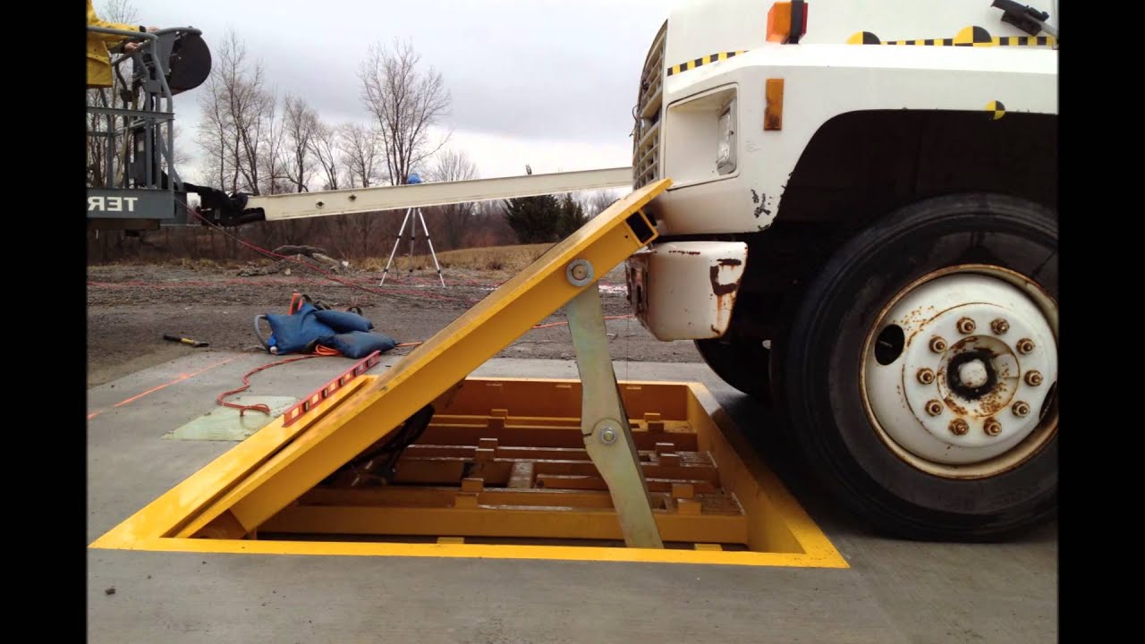
front braces 71. As an outcome, the affiliation settings up 72 may pivot and revolve to enable the collapse and expansion of the linkage settings up 72 throughout retraction and implementation of the bather 10. The linkage assemblies 72 cause motion of the wedge plate 16 to be restricted. If a car is taking find out a trip towards the released wedge plate 16(e. For example, in one condition, the safety and security legs link 86 may be expanded duringmaintenance of the barrier 10. When the safety legs 86 are released, the safety and security legs 86 sustain the weight of the wedge plate 16 against the surface area 12. Therefore, the training device 50 might be shut down, serviced, gotten rid of, replaced, and so forth. FIG. 5 is partial perspective sight of an embodiment of the surface-mounted wedge-style obstacle 10, highlighting the webcam 80 and the camera surfaces 82 of the lifting mechanism 50. Particularly, 2 camera surface areas 82, which are described as reduced web cam surfaces 83, are positioned below the web cam 80. The lower web cam surfaces 83 might be repaired to the surface area 12 (e. As an example, the lower camera surface areas 83 and the mounting plate 85 may create a single item that is secured to the anchor 30 by screws or other mechanical bolts. In addition, 2 web cam surface areas 82, which are referred to as top webcam surfaces 87, are positioned over the cam 80 and combined to (e. In various other embodiments, interfering layers or plates might be placed between the surface area 12 and the lower camera surfaces 83 and/or the wedge plate 16 and the top camera surface areas 87 As stated above, the web cam
80 translates along the camera surface areas 82 when the wedge plate click to investigate 16 is lifted from the pulled back position to the released setting. Additionally, as mentioned over, the spring setting up 54 (see FIG. 3 )might supply a pressure acting upon the camera 80 in the instructions 102 through spring rod 58, which might reduce the pressure the electromechanical actuator 84 is called for to relate to the cam 80 in order to actuate and lift the wedge plate 16. 1 )to the released placement(see FIG. 4). As revealed, the camera 80 includes track wheels 104(e. g., rollers), which call and convert along the cam surfaces 82 throughout procedure.